How we do it
One standardized building. Purpose-built for AI workloads.
The H building: 162.5 MW of on-site generation, 100 MW of net IT and ten integrated power blocks.
The H building.
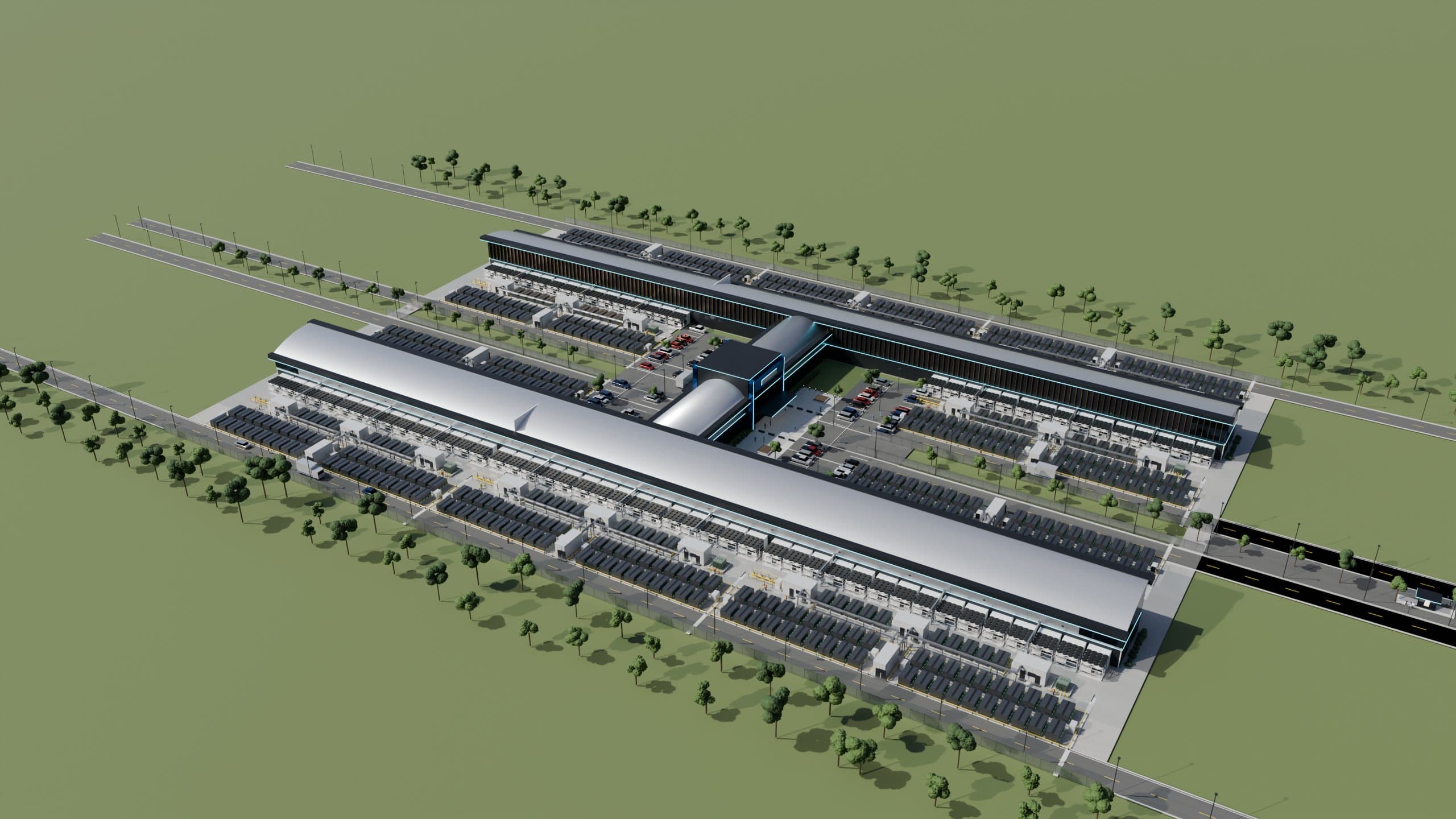
Two compute legs. One central connector. Power blocks along the outside edges.
Each H is designed for 100 MW net IT from ten integrated power blocks. Each block adds approximately 10 MW net IT, making capacity repeatable in useful increments.
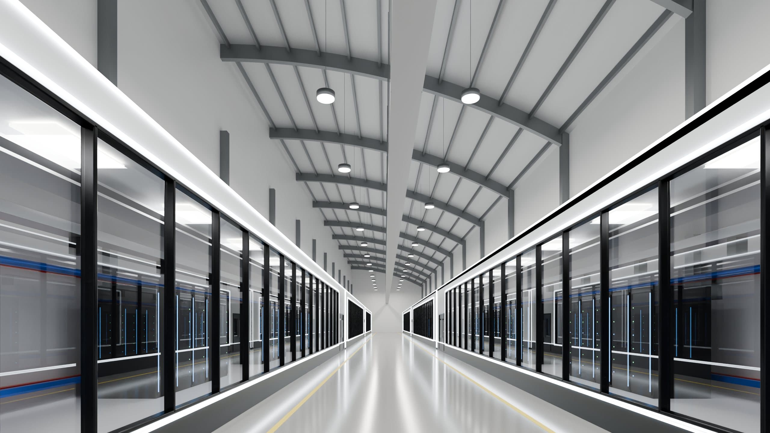
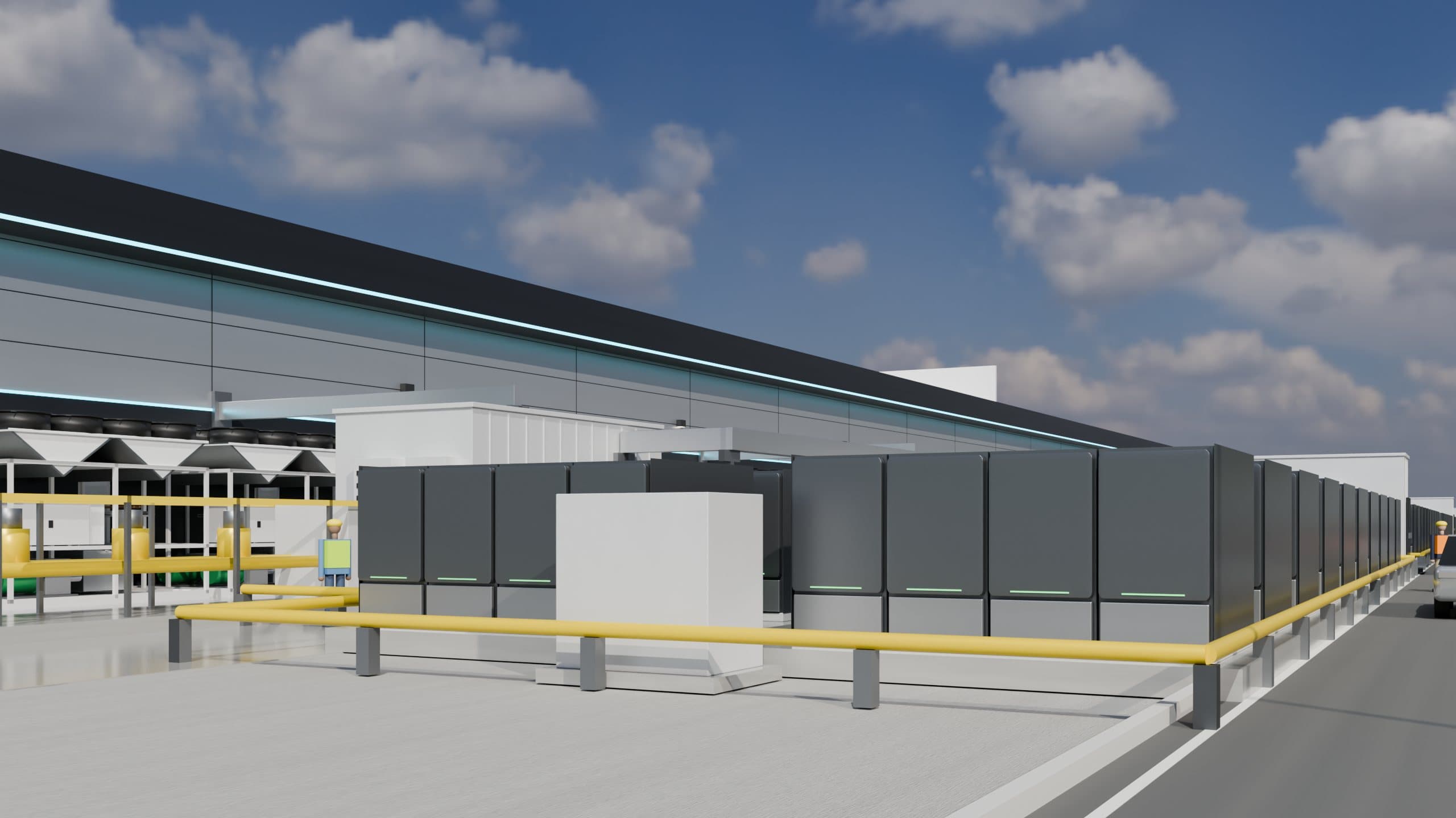
The power block.
On-site generation, standardized distribution and liquid cooling form a complete unit for AI compute.
10 MW net IT per power block
~3.34 MW IT per standard pod
16 compute positions per pod
AC today. DC tomorrow. Same building.
The AC/DC conversion stage is a swappable cassette. Run AC, DC or a mix, pod by pod, as AI hardware moves toward 800 V-class DC.
The brief specifies ±400 VDC with a center neutral. Generation, the building and cooling stay in place while the affected pod is reconfigured.
Power plant + building + cooling
These layers stay in place.
Other pods stay live
~3.34 MW IT per pod180–300 kW / rack
~3.34 MW IT per podOther pods stay live
~3.34 MW IT per podPod 2: AC, 180–300 kW per rack. Pods 1 and 3 remain live.
Concept illustration. A cassette change is planned work at the affected pod, not an instantaneous live switch.Fixed generation equipment and building infrastructure serve AC or DC cassettes. AC racks run at 180–300 kW; DC racks up to 480 kW. Other pods remain live during planned work on the selected pod. Concept illustration; a cassette change is planned work at the affected pod.
180 kW is where we start.
Designed for Vera Rubin-class systems, the standard starts at a 180 kW minimum per rack.
180 kW minimum rack rating
180–300 kW AC racks
Up to 480 kW DC racks
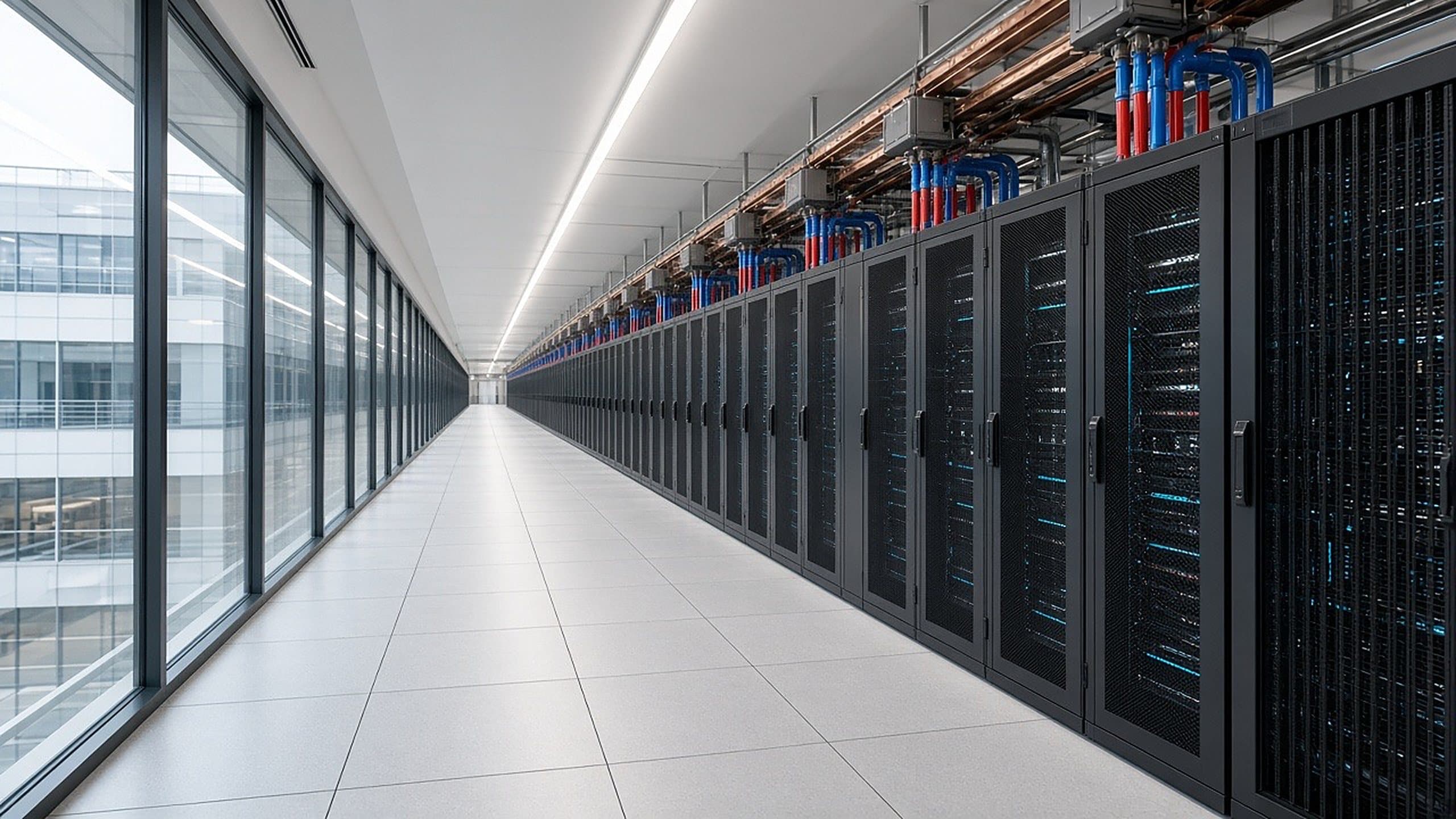
Direct to chip. Waterless heat rejection.
Liquid travels straight to cold plates on the chips. Exterior dry coolers reject the heat without an evaporative cooling process.
Dry heat rejection avoids evaporative cooling. Other campus water requirements depend on the site and design.