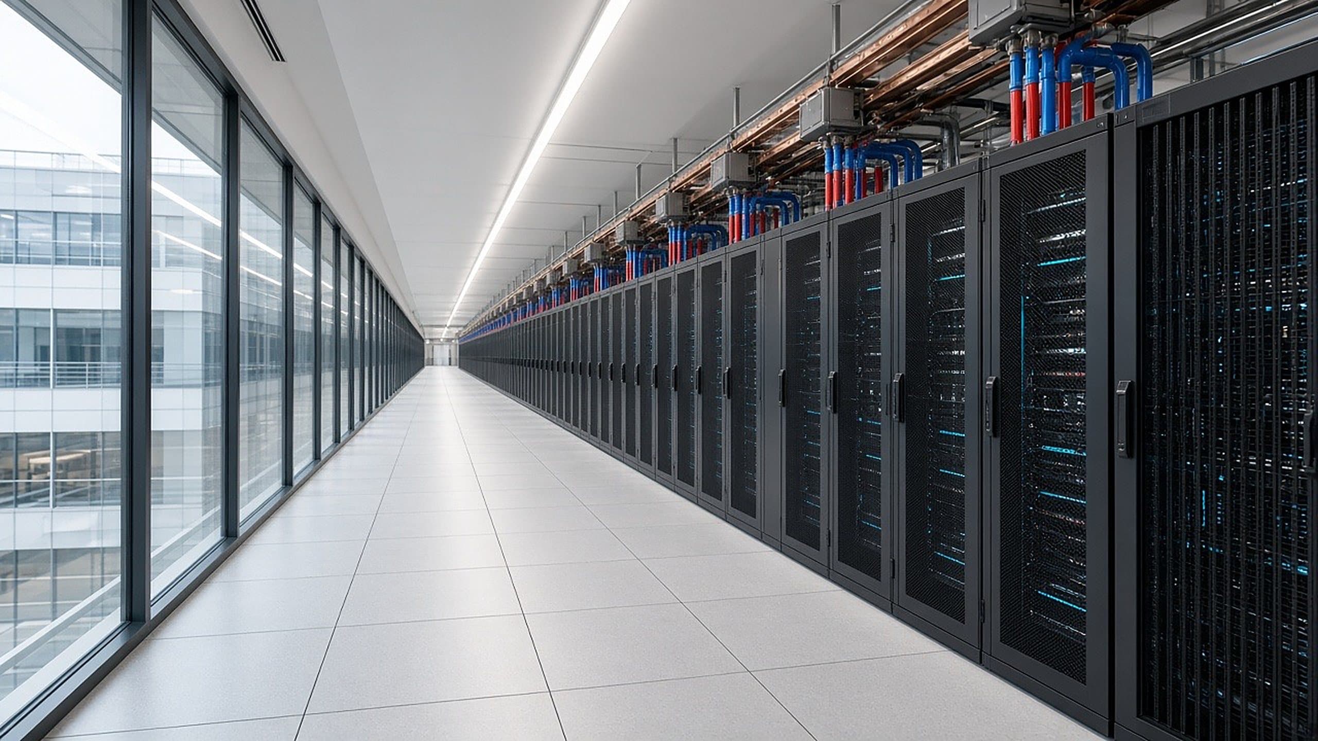
Our solution · Power to compute
Power and compute, engineered as one system for AI.
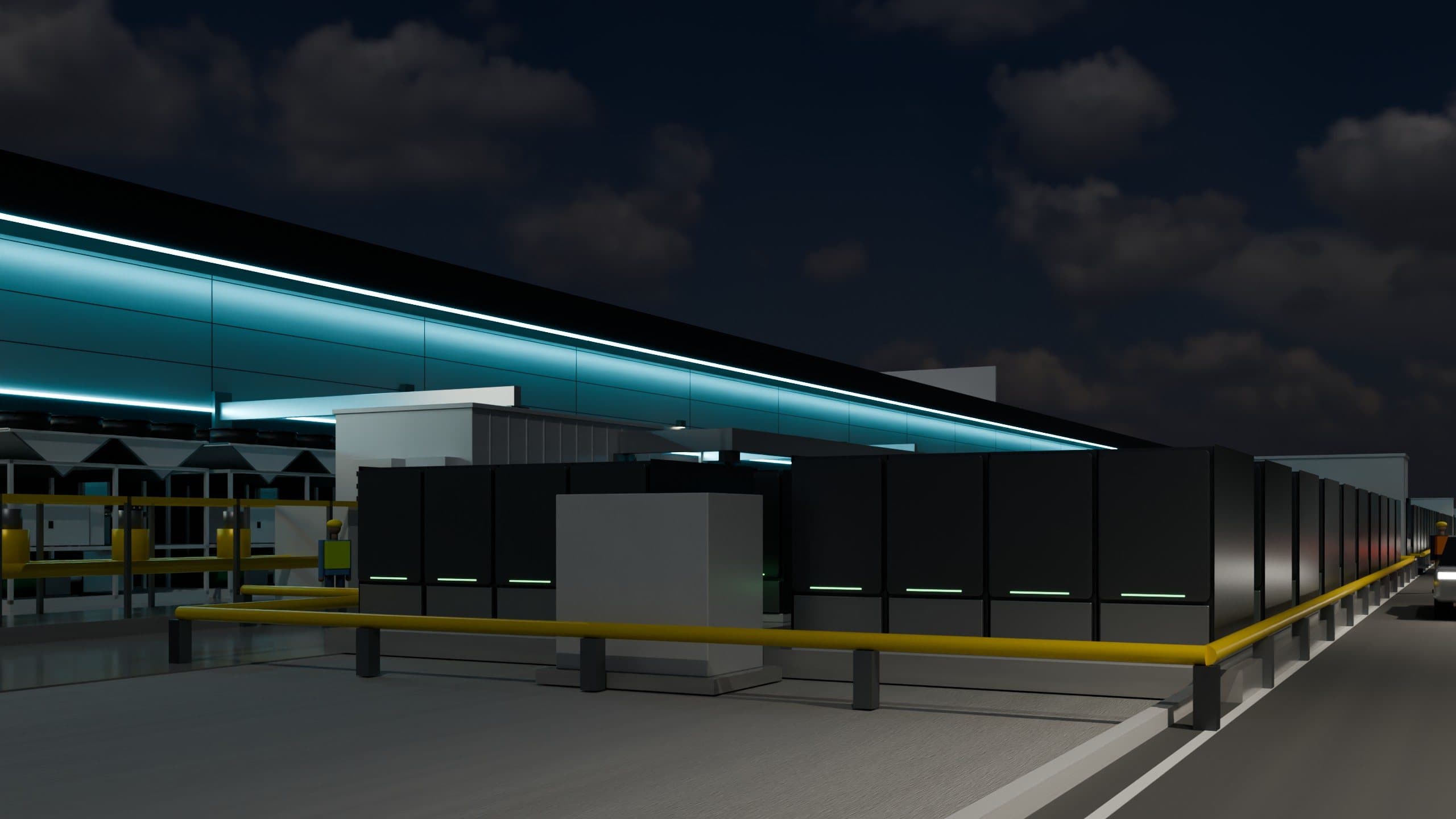
Dedicated fuel-cell blocks make power on site, behind the meter, and deliver it straight to AI racks. Hybrid campus configurations also include utility-fed capacity.
One integrated chain. Gas meter to AI rack.
On-site solid-oxide fuel cells convert natural gas into electricity electrochemically, rather than using an engine-driven generation process. Standardized distribution feeds a swappable AC or DC cassette and liquid-cooled AI racks.
- 01
Fuel supply
- 02
Solid-oxide fuel cells
- 03
Standardized distribution
- 04
AC / DC Cassette Swap
- 05
AI compute rack
AI tenants connect to finished power and cooling at the pod. DGEI’s proposed operating model brings the chain together under one interface.
View the original concept diagram
Open full-size original PNG ↗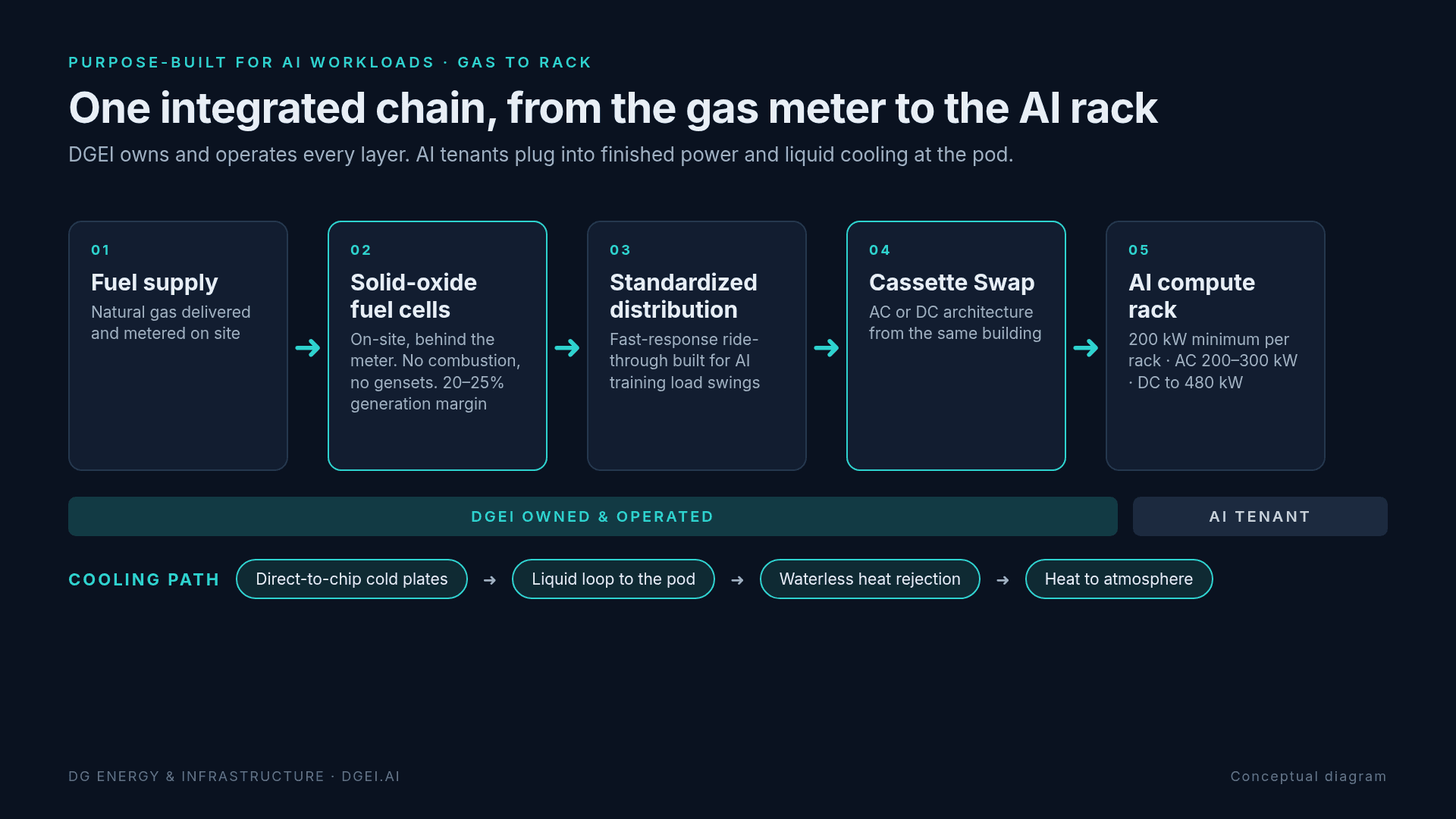
Fuel supply flows through on-site fuel cells, standardized distribution and a swappable AC/DC cassette to AI racks. Cooling connects chip cold plates to a liquid loop and waterless heat rejection.
Ten generation blocks. One microgrid.
Each power block provides self-contained power generation for its compute pods. All ten connect for shared redundancy, within a building and across multi-building campuses.
162.5 MW gross generation per H
20–25% design generation margin
99.999% designed uptime
Ten self-contained power blocks connect for shared redundancy. Design targets; not a statement of measured operating performance.
Ten approximately 10 MW net IT blocks share a campus microgrid. The design specifies 162.5 MW gross generation, 100 MW net IT per H, a 20–25% generation margin and 99.999% designed uptime. Design targets, not measured operating performance. Grid ties and export require utility agreements and approvals.
Built for how AI behaves.
AI training clusters move together. Their power draw spikes and drops in milliseconds.
Fast-response ride-through, generation margin and cooling are designed around those load swings, rather than an average enterprise server room.